STEP-TV
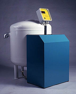
The STEP-TV function is eliminating the negative effects of air and gases within the heating system. Keeping the pressure in the system at the pre-set levels, STEP-TV safely prevents low pressure, thus the evaporation or cavitation in each part of the system. The pressure-free container serves for balancing any changes in the system volume by regulating changes in temperature. STEP-TV checks parameters of the system, removing from the system any free and dissolved gases. During the operation, it prevents gas bubbles to release as well as noise in radiators and circulation dysfunctions to occur. Any water lost from the system is automatically refilled. When the separate security of the sources of heat is not ensured by the pressure expansion tank, a process of „cycling“ may occur. Whenever it takes place, attaching a pressure expansion tank to STEP-TV.
Basic functioning
Maintaining constant pressure in the heating system automatically through self-controlled water-filling.
When necessary, the heating system is filled automatically with water from a pressure-free tank by means of a pump. Once the pressure in the system has exceeded the controller pre-set value, the electromagnetic valve lets the water flow into the pressure-free tank. This function enables safe, trouble-free and remote operation. In case of any system leakage, the flow of water into the system is automatically blocked by STEP-TV after a specified period of time and the equipment returns an error message, which can be transmitted to the control system of the source of heat.
Venting and degassing during operation
The process takes place within STEP-TV based on desorption which means that air and gases are eliminated from the hot-water system. Once STEP-TV has been installed within the system, heating water starts to flow through the equipment, whilst that contained in the pressure tank or in the piping by the pressure sensor and of the same pressure as that in the system is closed by a valve and a backflow valve. Opening the valve releases the pressure from the water. Connecting with the pressure-free tank reduces operating pressure to equal the atmospherical pressure, thus achieving the maximum elimination of the air and gases from the heating water. The water so treated is pumped back into the system under appropriate pressure, where the remainder of air and gases is absorbed from the problematic parts of the pipeline. The process of degassing is automatically adjusted to the conditions inside the system and controlled by a scheme selected automatically.
Physical treatment of water
Oxygen and other gases causing not only the air-lock of the system but also the oxygen corrosion of materials and successive damage of boilers, pumps and heat exchangers are removed from the circulating water. Adding STEP-TV a continuous-flow water softening filter produced by STEP TRUTNOV is possible by installing the device before the cold water supply /see A/.
Safeguarding the heating system
STEP-TV is protected against excessive working overpressure in accordance with ČSN 06 0830.
Dimensional table
| Type TV | Output power [kW] | System volume [l] | Tank capacity [l] | Input DN | Output DN | Water filling DN | Diameter [mm] |
|---|---|---|---|---|---|---|---|
| TV 01 | do 100 | do 1500 | 80 | 25 | Based on ČSN 06 0830 čl. 6.5.3 | From 15 to 25 | 550 |
| TV 02 | do 200 | do 2500 | 110 | 25 | 550 | ||
| TV 03 | do 300 | do 4000 | 200 | 25 | 550 | ||
| TV 06 | do 600 | do 5000 | 300 | 25 | 550 | ||
| TV 08 | do 800 | do 10000 | 400 | 25 | 600 | ||
| TV 18 | do 1850 | do 14000 | 540 | 25 | 650 | ||
| TV 45 | do 4500 | do 25000 | 1000 | 25 | 800 |
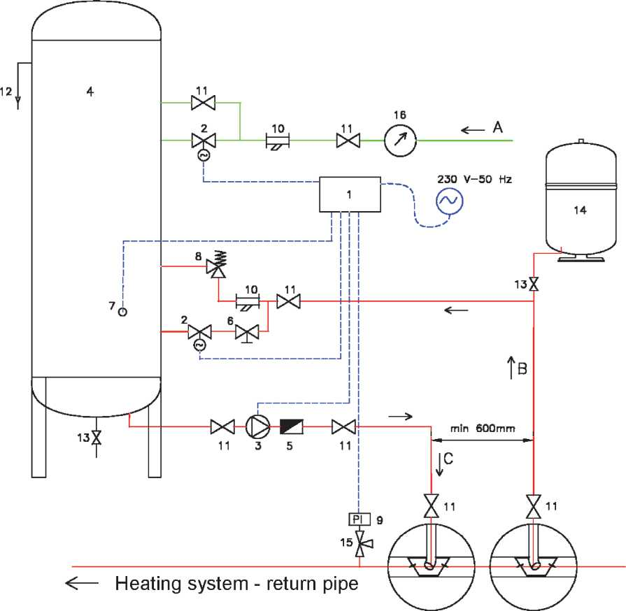
Recommended hydraulic diagram

Captions
| 1 | Programmable controller | 11 | Ball shut-off valve |
|---|---|---|---|
| 2 | Electromagnetic valve | 12 | Overflow |
| 3 | Pump refill | 13 | Ball discharge valve |
| 4 | Storage tank | 14 | Expansion tank - optional accessories |
| 5 | Backflow valve | 15 | Intercepting manometric valve |
| 6 | Control valve | 16 | Make-up water meter |
| 7 | Level sensor | A | Recharge of treated water |
| 8 | Mechanical pressure relief valve | B | Supply pipe from the heating system |
| 9 | Pressure sensor | C | Return pipe into the heating system |
| 10 | Filter |


