")
")
")
")
")
Boilers for burning whole bales of straw (600-6250 kW)
Type and capacity range: STEP-KS 600 ÷ 6,250 kW
Use
The equipment for burning whole bales of straw has been designed for heating of larger buildings (e.g. industrial premises, municipal heating plants, farm buildings, hotels, operating facilities, etc.).
Boiler type options
We can supply a basic type of boiler, which is a warm-water version, as well as hot-water boilers or steam boilers with/without a steam super heater upon customer’s demand.
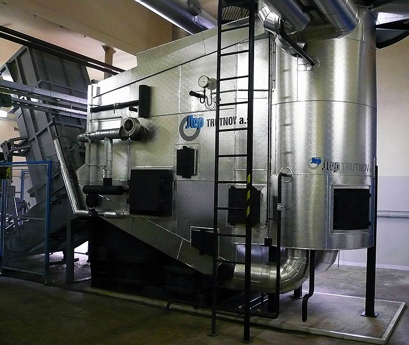
Boiler description
The equipment consists of a water-tube combustion chamber above a modified overfeed stoker, and a fire-tube exchanger. The combustion chamber is of a water-tube membrane type. The front part is fitted with an inlet opening for whole bales of straw. The bales are inserted by a special device above the front part of the stoke.
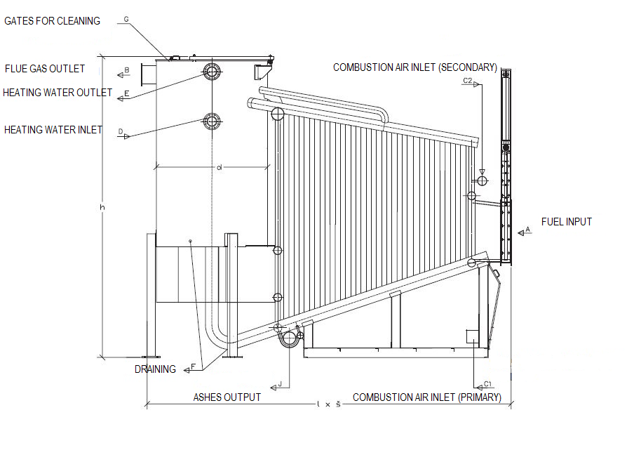
The boilers are supplied with all fittings including insulation and plating. An ash unloading screw conveyor is placed at the end of the stake. Flue gases go out of the combustion chamber to enter a vertical flue gas exchanger. The flue gas outlet from the exchanger is placed in the upper part and can be tailored to a specific position according to boiler room’s drawings.
Operation and control
There is a step automatic control of the boiler’s capacity with continuous scanning; it is determined by a value of combustion chamber’s vacuum as well as by a number of batches of fuel fed into the fireplace depending on the temperature of the boiler’s output water. The slave fan is operated according to a frequency rpm converter depending on O2 level in flue gases. An exhaust fan placed on the flue gas outlet controls the vacuum set in the chamber with a frequency speed converter.
Fuel
Squared bales of straw (rape&cereal straw, hemp, Uteusha energy sorrel), max. profile 1,250 x 1,200 mm, max. length 2,400 mm, max. humidity 20 %; medium pressed. Content of non-combustible matter (dust, sand): max. 0.4 %. Ash content max. 6 %. The bales must be completely bundled, they may not be deformed, and their humidity must be uniform. It is essential that the design of the fuel inlet opening or even of the combustion chamber be modified to match specific profiles of the bales. Each time the fuel type is changed, the combustion must be adjusted.
Boiler clearing and cleaning
The ash is unloaded from the chamber automatically by means of a screw transverse conveyor placed in the rear side of the chamber. The heat-delivery surfaces are cleaned mechanically by means of special brushes; and there is an easy-to-dismount door and a gate to collect ashes.
Transport of fuel
The fuel transport system comprises a belt conveyor and overfeed table placed in the fuel depot. The operator puts straw bales on a belt conveyor by e.g. fork lifter. The conveyor carries the bales, placing them on the overfeed table. The overfeed table is equipped with a device indicating presence of a straw bale, which gives a command to stop the feeding on the conveyor after the filling is completed. Before each bale is fed into the boiler, a water-cooled cover is opened first, and then closed automatically as soon as the bale is inserted.
The whole process of both feeding the fuel into the boiler and the metering of the material into the fireplace as such is completely automated based on boiler operating system commands.
Boiler parameters
| Boiler capacity | kW | 600 | 1000 | 1500 | 2000 | 2500 | 3000 | 4000 | 5000 |
|---|---|---|---|---|---|---|---|---|---|
| Max. temperature | °C | 110 | |||||||
| Max. working pressure | bar | 6 | |||||||
| Boiler efficiency at nominal capacity | % | 86 - 91 | |||||||
| Flue gas temperature at the boiler's outlet | °C | 160 | |||||||
| Fuel demand* | kg.h-1 | 174 | 291 | 436 | 581 | 726 | 872 | 1732 | 2166 |
| Flue gas volume* | Nm3.h-1 | 1577 | 2629 | 3943 | 5257 | 6571 | 7886 | 9364 | 11704 |
| Boiler length | m | 4,9 | 5,4 | 5,8 | 6,2 | 6,5 | 6,8 | 7,2 | 7,6 |
| Boiler width | 2,1 | 2,1 | 2,1 | 2,1 | 2,5 | 2,5 | 3,0 | 3,0 | |
| Boiler height | m | 4,5 | 4,5 | 4,7 | 5,1 | 5,4 | 5,7 | 6,1 | 6,5 |
| Boiler weight | kg | 12400 | 13200 | 14000 | 14800 | 16500 | 18400 | 20900 | 24100 |
| Volume of water | m3 | 3,60 | 4,75 | 5,85 | 7,10 | 9,30 | 10,90 | 14,50 | 19,40 |
*at nominal capacity, wood chip material humidity 20 %, and clean heat-delivery surfaces.
Drawing
Flowchart: Transport of fuel

02 – Overfeed table
03 – Inlet fuel neck with a cooled cover