Boilers for burning wood chips and bark (100-1000 kW)
Type and capacity range: STEP-KB 100 ÷ 1,000 kW
Use
This equipment for biomass combustion (mixtures of sawdust, strips, bark, forest wood chips, shavings etc. or grains) has been designed to heat buildings ( industrial premises, central and municipal heating plants, farm buildings, hotels, operating facilities, etc.).
Boiler type options
We can supply a basic type of boiler, which is a warm-water version as well as hot-water boilers or steam boilers upon customer’s demand.
Boiler description
The combustion system consists of two self-contained units. There is a combustion chamber with a solid cast iron grate including a heat-resistant lining, and a STEP-KB boiler.
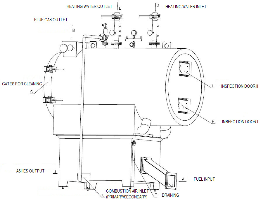
The supporting part of the chamber is formed by a perimeter steel frame, which serves as a base for a flue gas exchanger at the same time. The chamber has a grate that is construed for a fuel with grain size up to 50 mm. The inner lining of the boiler comprises an insulating layer and heat-proof fire-clay lining. The fire-brick arch is lined with heat-resistant bricks placed in funicular arches. The second unit comprises a horizontal fire-tube exchanger. It is a four-flue exchanger containing an inlet chamber in the rear in its bottom part, and front/rear turnover chambers. Flue gases going out of the fourth flue fire-tubes in the rear part of the exchanger are exhausted into a flue gas ducting through a flue outlet. The flue gas outlet can be tailored to the boiler room’s position according to boiler room’s design.
Operation and control
The boiler’s capacity is controlled automatically with continuous scanning; it is determined by a value of combustion chamber’s vacuum as well as by a number of batches of fuel fed to the chamber depending on the temperature of the boiler’s output water. The combustion air is supplied into the chamber by a single fan. Having entered the boiler, the air is split by a damper to primary air and secondary air. The primary air flows under the grate and side bricks of the combustion chamber, while the secondary air flows through the flame outlet opening of the chamber to support a proper fuel burn-up with minimum level of NOx and CO produced. An exhaust fan placed on the flue gas outlet controls the vacuum set in the chamber with a frequency speed converter.
Fuel (2 options)
a) Wood biomass (a mixture of sawdust, strips, bark, forest wood chips, shavings etc.), min. heating value 10.1 MJ/kg, humidity up to 40 %; e.g. beech, birch, oak or spruce. Content of non-combustible matter (dust, sand): max. 0.4 %. Size of the wood waste matter up to o 50 mm.
b) Grains (wheat, oat, barley, rye, maize, etc.). Content of non-combustible matter (dust, sand): max. 0.4 %.
Boiler clearing and cleaning (2 options)
a) Automatic – The ash is unloaded from the chamber automatically by means of a screw transverse conveyor placed in the rear side of the chamber. The heat-delivery surfaces are cleaned by hand, which is done mechanically by means of special brushes and there is an easy-to-dismount door and gate to collect ash.
b) By hand – The ash must be picked by hand from the chamber to an ash-bin via an ash door. The heat-delivery surfaces are cleaned by hand, which is done mechanically by means of special brushes, and there is an easy-to-dismount door and gate to collect ash.
Fuel transportation (2 options)
a) Hydraulic transport of fuel
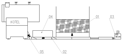
Unloading silo – Fuel is transported from the silo by agitation of an axial feeding bar fitted with a large number of unloading wedges. The feeding bar is driven by a hydraulic cylinder. The wedges on the feeding bars are designed to pick up the fuel placed in the silo when moving towards the overflow to the hydraulic feeder, and to pass under the fuel when going back. Thus, the fuel is transported to the hydraulic feeder that is placed crosswise to the moving of the feeding bar; here it is collected and moved forward to the boiler’s chamber.
Hydraulic feeder – The feeder works on an identical basis as does the system of unloading from the silo; it is integrated into the control circuit of the boiler, which means that it is activated or deactivated depending on the heat off-take from the boiler (based on the output water temperature from the boiler). The benefit of this system is that the flow of the fuel can be separated completely at two points, i.e. the wall between the silo and boiler areas and the wall between the refuelling and fireplace areas. This is enabled by a strong counter-knife placed at the points mentioned above, which blocks the feeders equipped with cutting knives each time a feeding cycle is completed or the equipment stops.
This not only provides for the safest protection from any back burning, but also for cutting and easy transporting of larger logs or bark contained in the fuel to the chamber.
b) Fuel transport by screw conveyors
The fuel is transported from the silo by a screw conveyor that is positioned to the boiler perpendicularly. The silo has a volume of 2.0 m3. A screw conveyor (O150 mm ) including a planet gear and stirring sheet metals on the inclined silo walls is integrated in the bottom part of the silo. The upper part of the silo is fitted with an opening for filling of the fuel. The other end of the screw conveyor is directly screwed to the boiler’s chamber (more specifically, on an inlet fuel flange). The filling screw conveyor is equipped with a fire-extinguishing device (e.g. a thermostatic water valve with a strap-on temperature sensor) connected to a water supply system.
Boiler parameters
| Boiler capacity | kW | 100 | 190 | 300 | 400 | 500 | 600 | 800 | 1000 |
|---|---|---|---|---|---|---|---|---|---|
| Max. temperature | °C | 110 | |||||||
| Max. working pressure | bar | 6,0 | |||||||
| Boiler efficiency at nominal capacity | % | 85 - 89 | |||||||
| Flue gas temperature at the boiler's outlet | °C | 175 | |||||||
| Fuel demand* | kg.h-1 | 45 | 86 | 135 | 180 | 225 | 260 | 347 | 433 |
| Flue gas volume* | Nm3.h-1 | 234 | 445 | 702 | 936 | 1170 | 1404 | 1872 | 2340 |
| Boiler length | m | 1,8 | 2,3 | 2,8 | 2,8 | 3,0 | 3,0 | 3,2 | 3,2 |
| Boiler width | m | 1,0 | 1,2 | 1,3 | 1,5 | 1,5 | 1,7 | 1,8 | 1,9 |
| Boiler height | m | 2,7 | 3,0 | 3,2 | 3,4 | 3,4 | 3,6 | 3,7 | 3,6 |
| Boiler weight | kg | 2090 | 2550 | 3020 | 3450 | 3980 | 4410 | 5090 | 5675 |
| Volume of water | m3 | 0,89 | 1,25 | 1,62 | 2,00 | 2,43 | 2,91 | 3,28 | 3,55 |
*at nominal capacity, wood chip material humidity 40 %, and clean heat-delivery surfaces.
Drawing

Flowchart: Transport of fuel

02 – Hydraulic feeder
03 – Hydraulic unit
04 – Filling interspace
05 – Transport tube into the boiler


