Boilers for burning whole bales of straw (100-1000kW)
Type and capacity range: STEP-KS 100 ÷ 1000 kW
Use
The biomass burning equipment (burning whole bales of straw in a vertical position) has been designed for heating of smaller buildings (e.g. industrial premises, municipal heating plants, farm buildings, hotels, operating facilities, etc.). The fireplace can be modified for combustion of wood waste (wood chips, bark, pellets), corn, chaff, etc.
Boiler type options
A basic type of a boiler, which is a warm-water version as well as a hot-water version can be supplied upon customer’s demand.
Boiler description
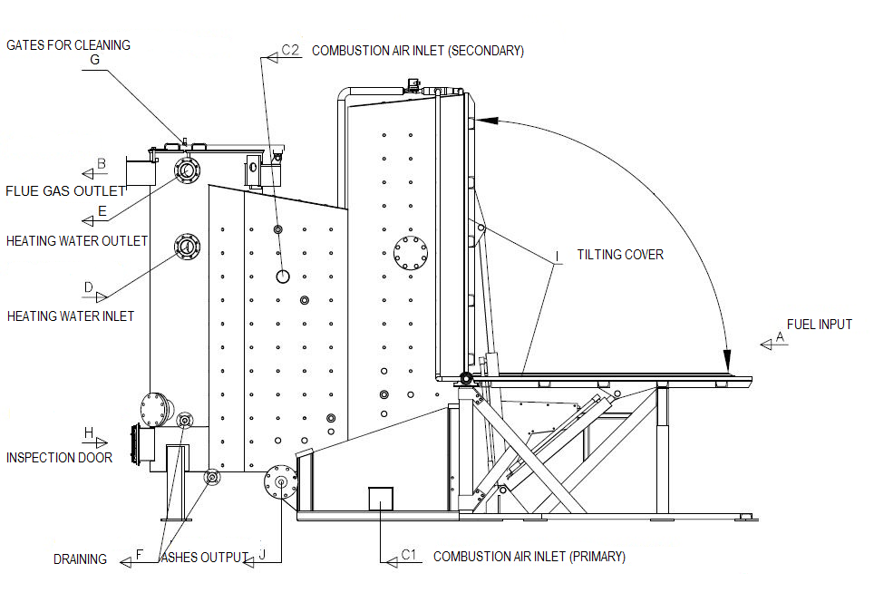
The STEP-KS boiler consists of a water-cooled combustion chamber, an overfeed stoke, and a vertical flue gas exchanger. The combustion chamber is divided in two parts by a water-cooled cross-member. The front part serves for placing the bales of straw vertically. The front chamber includes a cooled tilting cover serving to relocate the bale from a vertical position to a horizontal position when feeding fire. Behind the cross-member, there is a rear part of the chamber, where the fuel is combusted. The combustion chamber is mounted on an overfeed transversal stoke operated by a hydraulic system. In the bottom, there is a screw conveyor for automatic clearing at the end of the stoke. Flue gases going out of the combustion chamber are exhausted downwards along a flue gas exchanger’s casing to enter the exchanger. The flue gas outlet from the exchanger is placed in the upper part and can be tailored to the boiler room’s position according to drawings. The boilers are supplied with all fittings including insulation and plating.
Operation and control
There is a step automatic control of the boiler’s capacity with continuous scanning; it is determined by a value of combustion chamber’s vacuum as well as by a number of stoke cycles depending on the output temperature of the boiler’s circulating water. The primary air is supplied by the openings on both sides of the chamber under the grate, while the secondary air is supplied by a fan to the chamber to support a proper fuel burn-up with minimum level of NOx and CO produced. An exhaust fan placed on the flue gas outlet controls the vacuum set in the chamber with a frequency speed converter, and sucks primary air under the stoke.
Fuel
Squared bales of straw (rape&cereal straw, hemp, Uteusha energy sorrel), max. profile 1,250 x 800 mm, max. length 2,200 mm, max. humidity 20 %; medium pressed, max. ash content 5 %. Content of non-combustible matter (dust, sand): max. 0.4 %. The bales must be completely bundled, they may not be deformed, and their humidity must be uniform. It is essential that the design of the fuel inlet opening or even of the combustion chamber be modified to match specific profiles of the bales.
Each time the fuel type is changed, the combustion must be adjusted.
Boiler clearing and cleaning
The ash is unloaded from the chamber automatically by means of a screw transverse conveyor placed in the rear side of the chamber. The heat-delivery surfaces are cleaned mechanically by means of special brushes, and there is an easy-to-dismount door and gate to collect ash.
Transport of fuel; Hydraulic transport of fuel
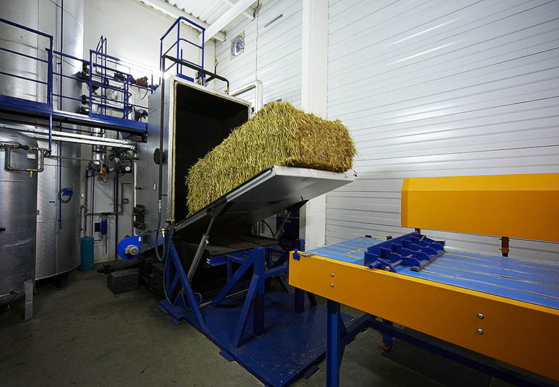
For automatic transport of the fuel (i.e. bales of straw) into the boiler, a working platform with a pushing plate actuated by a hydraulic piston is used. The working platform is integrated into the boiler’s control circuit, which means that it works automatically upon the command to feed the fuel in the boiler. The bales are loaded on the platform by a handling device such as a forklift truck or a crane track, which takes the bale from the storage into the boiler room and place it on the working platform in front of the pushing plate.
When command to feed the fire is given (i.e. the bale of straw had burnt up in the boiler with the sensor signalling an empty space in the front part of the combustion chamber), the cover is tilted and open. As soon as the cover is tilted, the bale of straw is relocated automatically from the working platform onto the tilting cover by the hydraulic piston with the pushing plate. Subsequently, the tilting cover closes, the bale of straw is fed in a vertical position and is ready for burning.
Boiler parameters
| Boiler capacity | kW | 100 | 350 | 1000 |
|---|---|---|---|---|
| Max. temperature | °C | 110 | ||
| Max. working pressure | bar | 4,0 | ||
| Boiler efficiency at nominal capacity | % | 86 - 90 | ||
| Flue gas temperature at the boiler's outlet | °C | 180 | ||
| Fuel demand* | kg.h-1 | 52 | 104 | 178 |
| Flue gas volume* | Nm3.h-1 | 402 | 804 | 1378 |
| Boiler length | m | 5,1 | 5,3 | 5,5 |
| Boiler width | m | 1,8 | 1,8 | 1,8 |
| Boiler height | m | 3,7 | 3,7 | 3,7 |
| Boiler weight | kg | 5590 | 5920 | 6410 |
| Volume of water | m3 | 1,85 | 2,10 | 2,45 |
*at nominal capacity, wood chip material humidity 20 %, and clean heat-delivery surfaces
Drawing

Flowchart: Transport of fuel

02 – Pushing plate
03 – Tilting cover


